The EzloPi smart devices provide automation through simple, customizable use with our open-source EzloPi platform, making daily life easier and improving human-machine interactions.
Before moving into this example, it is very important to know about the device registration, provisioning and converting the ESP32 device into an EzloPi device along with knowledge of Web Flasher, MiOS Mobile Application for Android/iOS and the MiOS Web Application.
1. About this example
The Hall effect sensor is a transducer that detects changes in magnetic fields. When a magnetic field is present, it generates a voltage proportional to the strength of the field. This voltage can be used to determine the presence, strength, or orientation of a magnet or magnetic field source.
The EzloPi device based on ESP32 when combined with the Hall effect sensors can prove to be a valuable component for detecting magnetic fields and various applications like proximity sensing, rotation measurement, and many more.
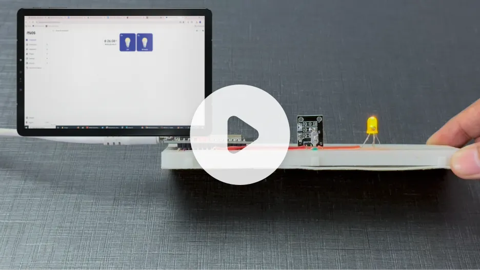
2. Project Demonstration Video
Welcome to the project demonstration video section. The following video showcases the key aspects of Detect tilt by using Tilt Switch Module KY-017 Mercury Tilt Switch and LED, providing a visual walkthrough of its implementation.
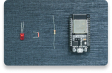
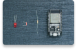
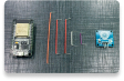
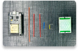
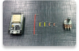
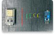
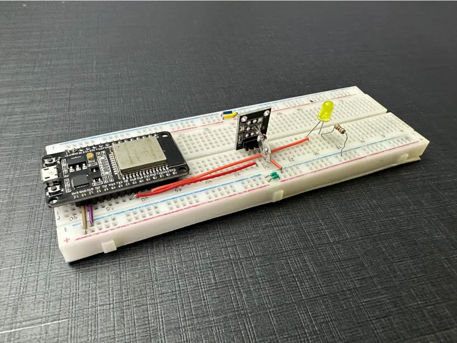
3. Circuit Diagram & Interface
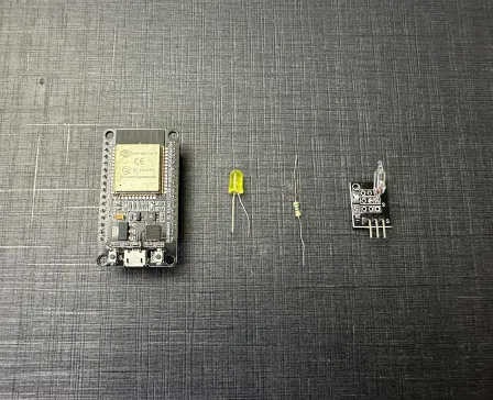
The following components are required for interfacing with the EzloPi device:
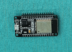
- ESP32 as an EzloPi smart device.
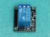
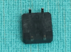
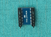
- KY-017 Tilt Switch Module.
- LED with 100 Ohm Resistor
The wiring diagram of ESP32 30 pin is represented as follows:
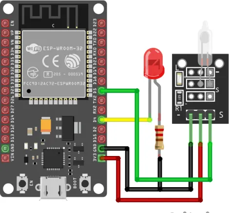
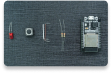
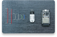
The following connections are made in order to complete the circuit setup.
From ESP32 to KY-017:
| ESP32 | KY-020 |
| VCC | Vin |
| GND | GND |
| D5 | S (Signal) |
From ESP32 to LED & Resistor:
| ESP32 | LED | Resistor |
| GND | - | 1st Terminal |
| D4 | Anode | - |
| - | Cathode | 2nd Terminal |
4. Interfacing the Tilt Switch Module using the EzloPi Web Flasher:
1. Set up your device/hardware by visiting config.ezlopi.com
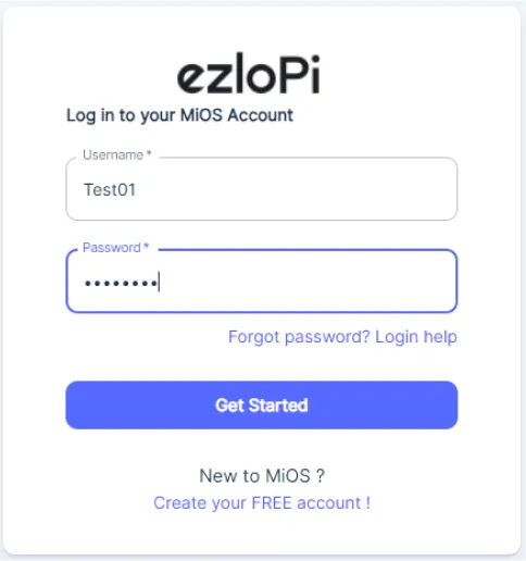
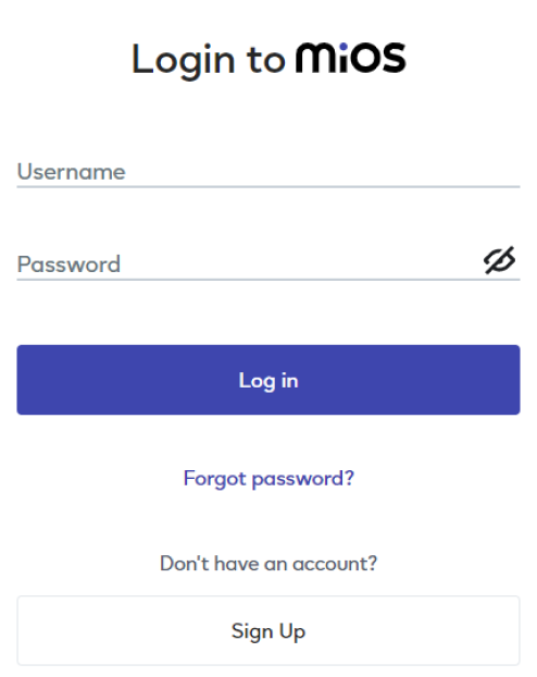
- Log in using the credentials which you just set earlier while signing up.
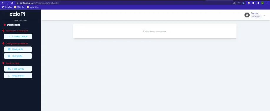
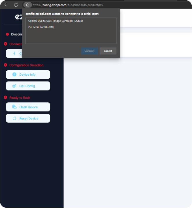
- Now, click on the Connect Device button and a pop-up window will appear.
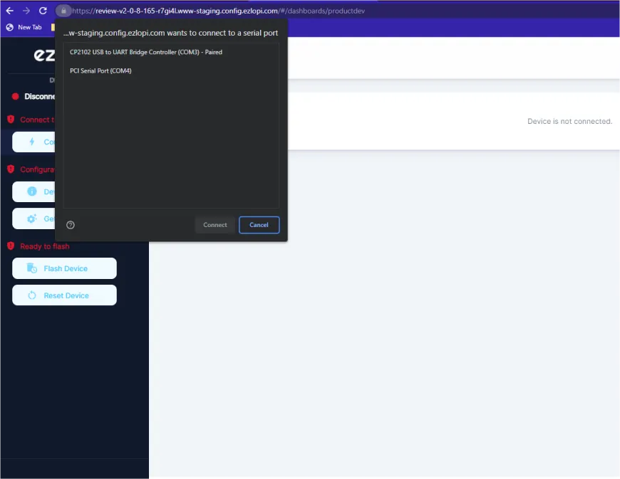
- Now, select COM Port to which your ESP32 device is connected. In our case, the COM3 port is used.
Click Connect
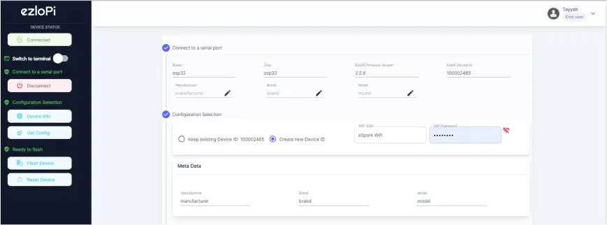
- If you are new to this and it's your first time configuring, select Create new Device ID. Enter Wifi SSID and Wifi Password.
- In the Device Configuration, tab click on Digital Input.
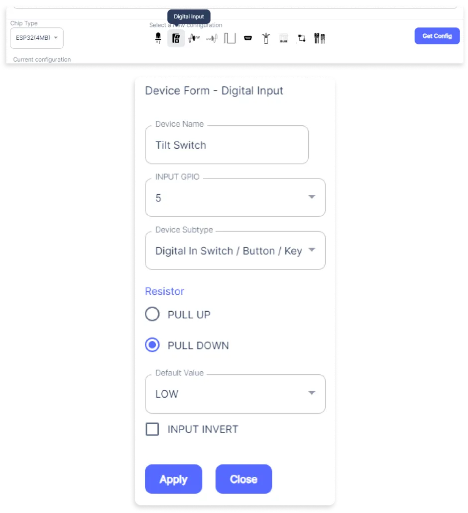
- The Digital Input window will open for inputting the following parameters:
- Set a Device name of your choosing. In our case, we set it to the Tilt Switch.
- Set INPUT GPIO to 5.
- Set Device Subtype to Digital In Switch / Button / Key.
- Set Resistor to PULL DOWN.
- Now Click the Apply button.
- In the Device Configuration, tab click on Digital Output.
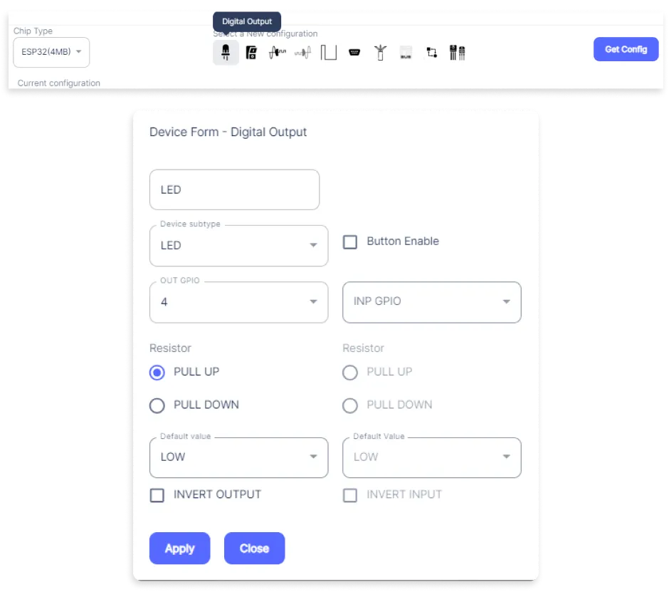
- The Digital Output window will open for inputting the following parameters:
- Set a Device name of your choosing. In our case, we set it to the LED.
- Set Device Subtype to LED.
- Set OUT GPIO to 4.
- Set Resistor to PULL DOWN.
- Now Click the Apply button.
- After clicking the apply button you can see a table of your setting in the device configuration tab.
- Press the Flash Device button.
- A window will appear on the bottom right side of the screen displaying “Please press BOOT button while flashing begins.”
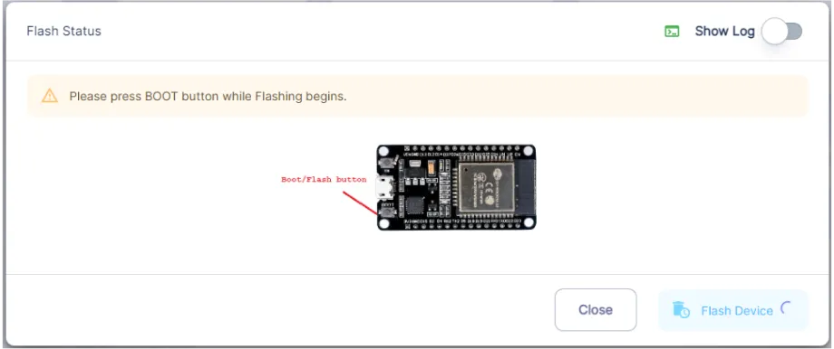
- Hold the BOOT button down until the next window appears on the bottom right side of the screen which says “Installation prepared. Please release the boot button now.”
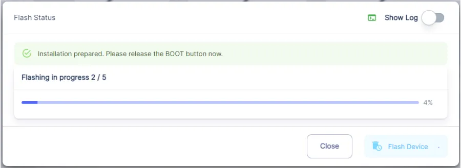
- Release the BOOT button from your ESP32 when this pop-up on the bottom right window appears.
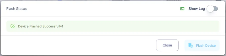
- After some time, a popup will appear saying Device Flashed Successfully! This means that your device has been set up successfully.
5. MiOS Web Dashboard
- After configuring the controller with the EzloPi web flasher, head to ezlogic.mios.com
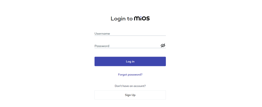
- Use the same credential to log in that you used for configuring the controller with the web flasher.
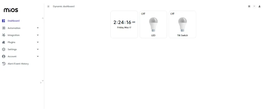
- As seen in the MiOS web dashboard above, the Tilt Switch and LED tiles are visible. For now they both are in off state.
MeshBots:
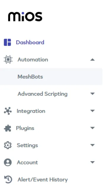
- On the left side of the screen under Automation, click on MeshBots.
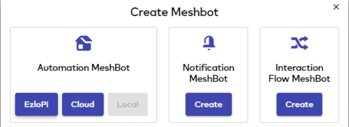
- On meshbot screen, click on Create new MeshBot button present on the top right corner of the screen.
- After clicking on Create new MeshBot you will see new options, click on EzloPi.
- On the next screen you will see that we can create a name of our choosing, in this case we write it as Test001.
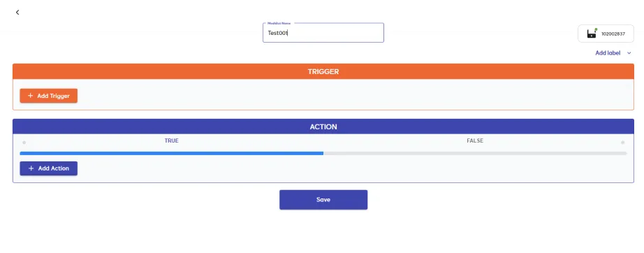
- In the trigger tab you can set the TRIGGER for your device and in the ACTION tab you can set the action to be performed based on the trigger which you have created.
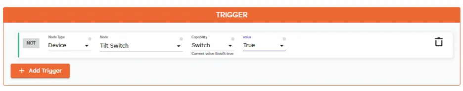
- Set these values in TRIGGER section:
- Set Node Type to Device.
- Set the Node to Tilt Switch.
- Set the Capability to Switch.
- Set the value to True.
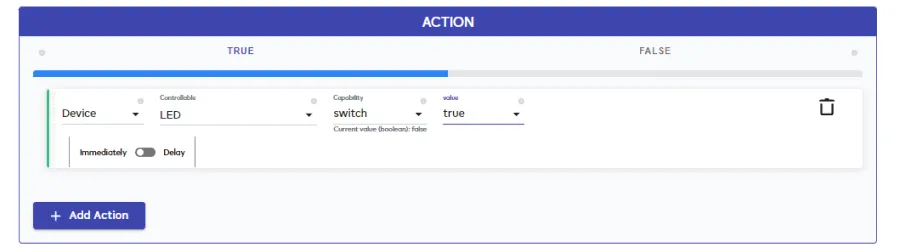
- Set these values in the True part of the ACTION section.
- Set Node Type to Device.
- Set Controllable Type to LED.
- Set the Capability to Switch.
- Set the value to true.
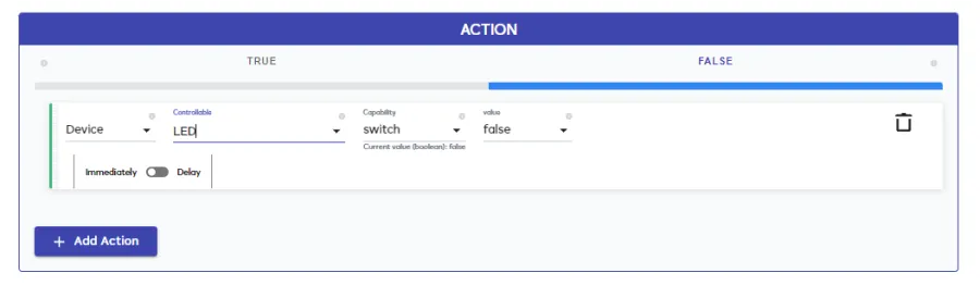
- Set these values in the False part of the ACTION section.
- Set Node Type to Device.
- Set Controllable Type to LED.
- Set the Capability to Switch.
- Set the value to false.
- After clicking the apply button you can see a table of your setting in the Current configuration tab.

- After clicking the save button you can see this screen on the top right corner of the screen.
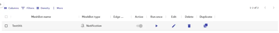
- Here you can see your saved MeshBot. Now click on Dashboard.
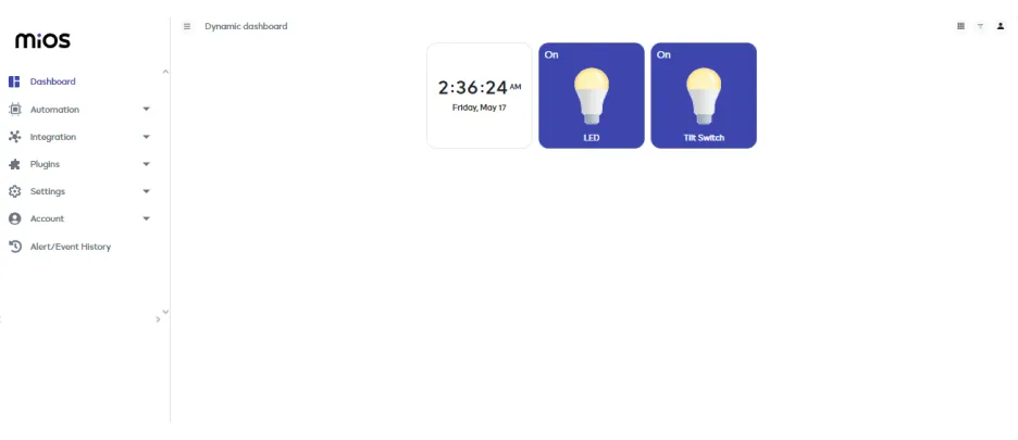
- As seen in the MiOS web dashboard above, the Tilt switch sensor tile is visible which is triggered and the LED gets turned on because of the rules we have set in the meshbot.
6. MiOS App
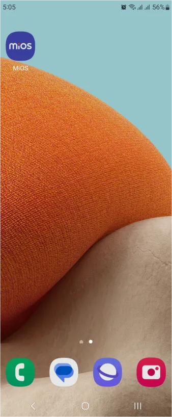
You can download the MIOS Android app from the Google Play Store and Apple App Store.


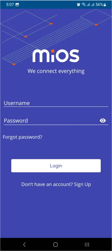
- After downloading the app, proceed to install the application and open it.
- Using the MIOS mobile application, create a new Ezlo Cloud account using the sign-up option. If you already have an account, you may proceed to log in.
- After successfully logging in, you will be able to see the number of controllers connected such as a lamp, fan, or any other device in the MiOS app. Tap on any controller of your desired ID:
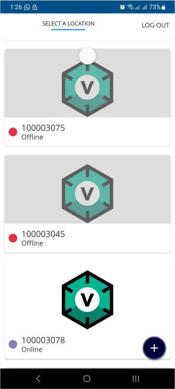
- You will be able to see the status of your controller whether it is online or offline. Access the device dashboard, and tap the device. The following view of the dashboard will appear:
- After opening the dashboard, you will be able to see the tile of your connected device.
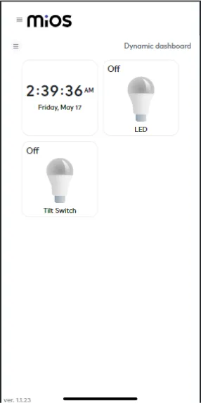
- As seen in the MiOS app above, the Tilt switch sensor and LED tiles are visible. For now they both are in off State.
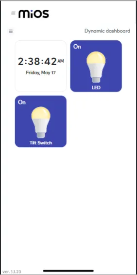
- As seen in the MiOS app above, the Tilt switch sensor tile is visible which is triggered and the LED gets turned on because of the rules we have set in the meshbot.