NOTE: Before moving into this example it is very necessary to know about the device registration, provisioning and converting the ESP32 device into an EzloPi device along with knowledge of Ezlogic desktop app. All these information can be collectively found in EzloPi User manual document. knowledge of the Ezlogic desktop app. All this information can be collectively found in the EzloPi User manual document
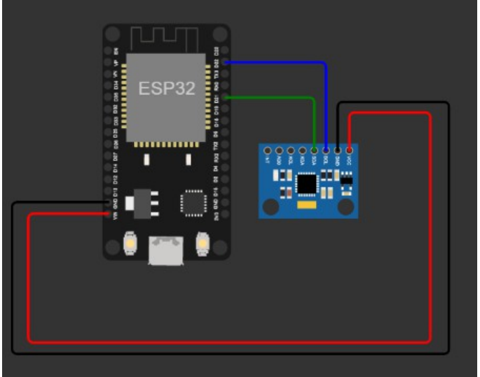
1 ESP32 and MPU6050 I2C circuitry setup
For interfacing and using the I2C MPU6050 sensor we will be needing following components:
1. An MPU6050 I2C sensor.
2. ESP32 device for converting it into EzloPi smart device
3. Power source for ESP32
The wiring diagram can be represented as:
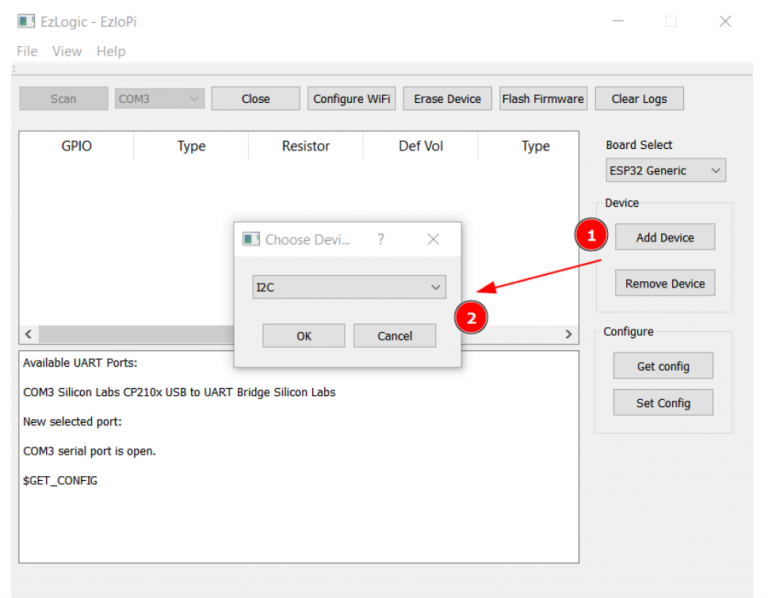
2 Adding MPU6050 I2C to the device from Ezlogic Desktop app
Note that before moving to add any device a new device should be added and which should be accessible from the Vera mobile app.
Also, note that for this example purpose we will be adding the Relay under the EzloPi serial
100004031 < update device serial here >
Device addition will be started with the button Add device in the UI as above. From the dropdown shown at 2 select I2C, furthermore we need to configure the sensor we are using i.e. MPU6050.
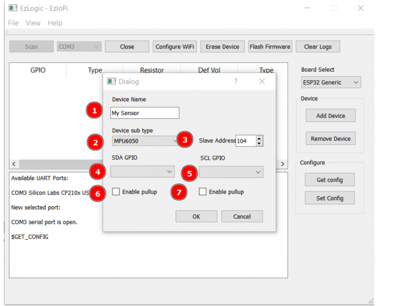
As in the above snapshot:
1. Name the device
2. Set sensor type in the UI
3. Add the correct slave address
4,5. select the correct GPIO pins
6,7. If no I2C bus pullup in the circuit enable them from UI.
After it is being configured, send the configuration to ESP32, which will command the device to add the I2C device on the bus